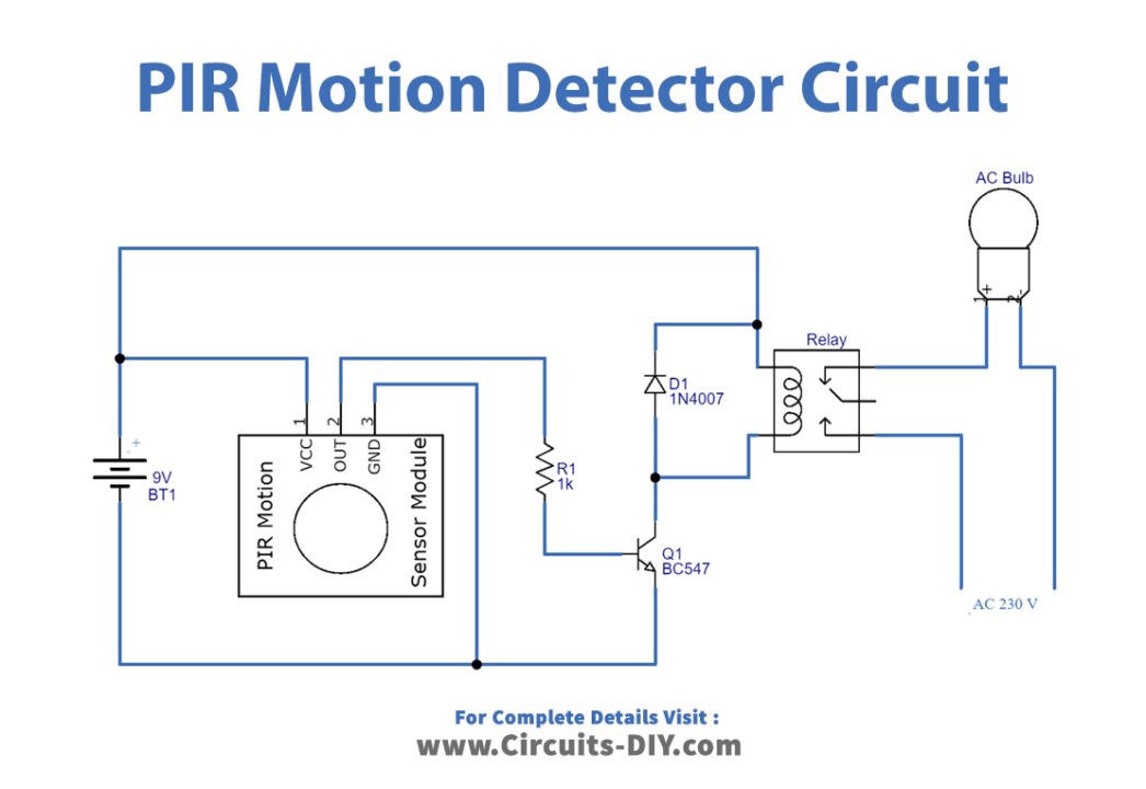
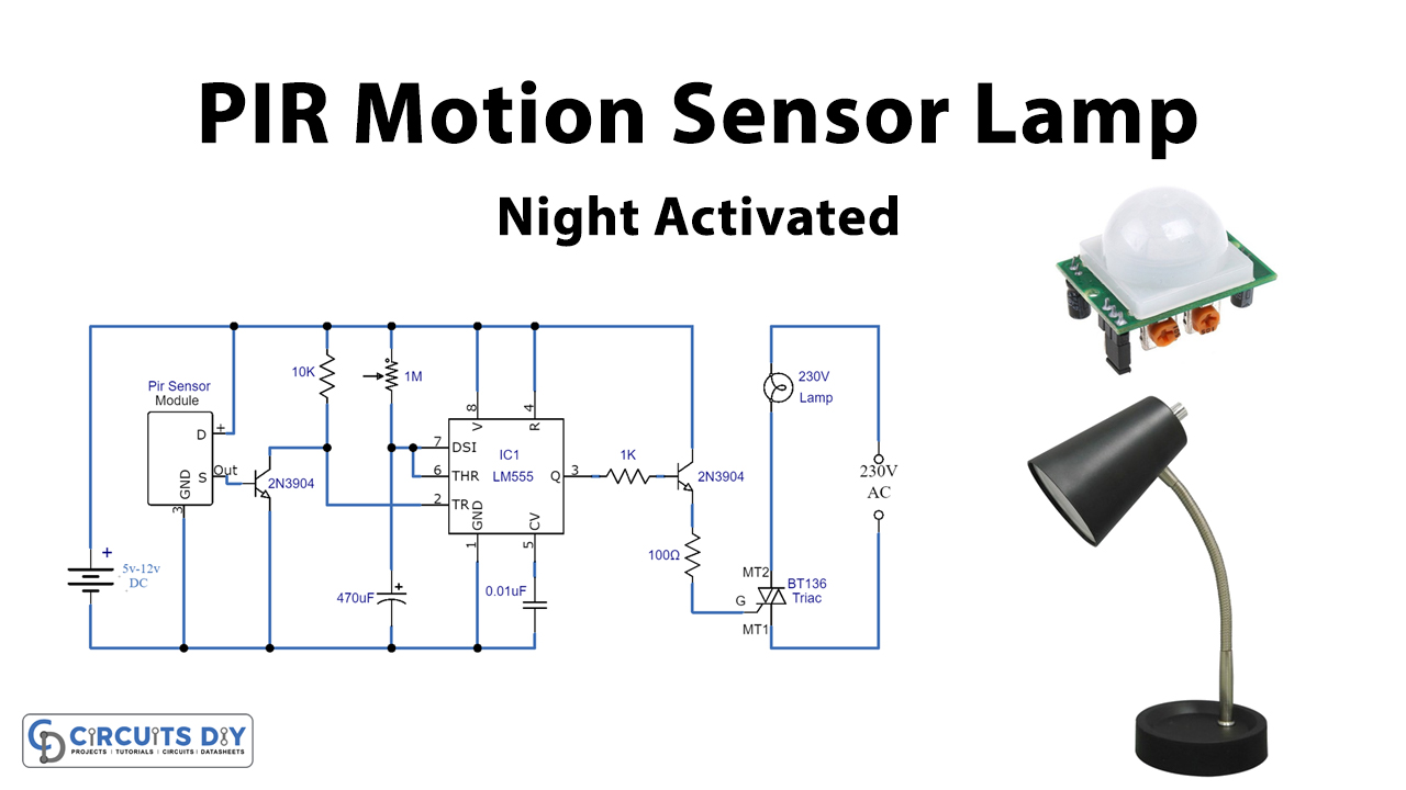
Simple PIR Motion Detector Circuit
Passive Infrared Sensor (PIR) is very useful module, used to build many kinds of Security Alarm Systems and Motion Detectors. It is called passive because it receives infrared, not emits. Basically PIR sensor detects any change in heat, and whenever it detects any change, its output PIN becomes HIGH.

Arduino With PIR Sensor for motion detector TECHATRONICS
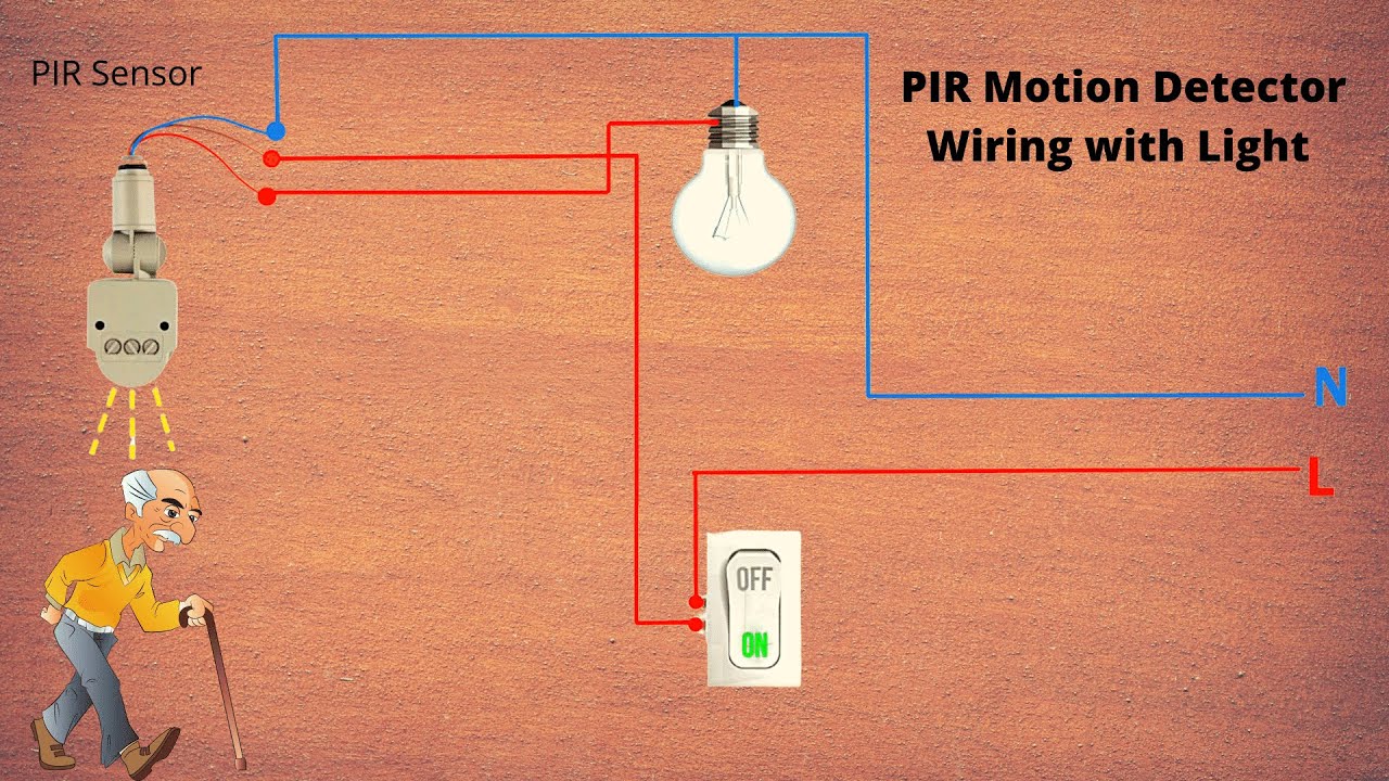
The wiring diagram of a PIR motion sensor typically includes three main components: the sensor itself, a power source, and a load. The sensor is responsible for detecting motion and sending a signal to the load. The power source provides the necessary electrical energy for the sensor to operate. The load can be any device, such as a light or an.

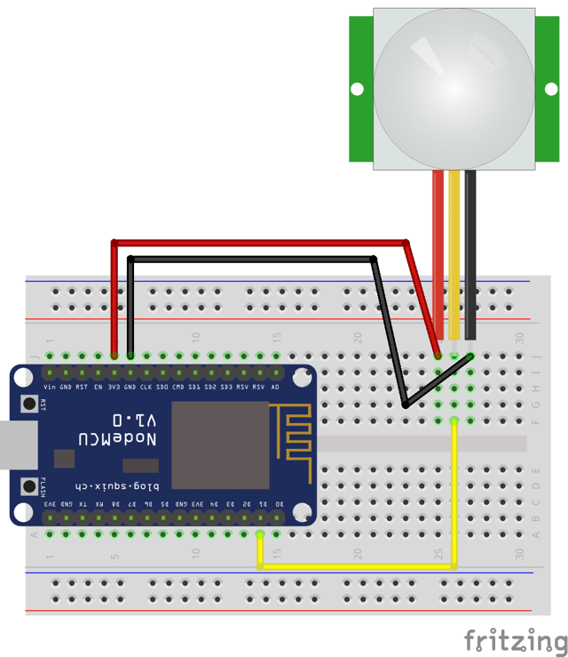
ESP8266NodeMCUPIRMotionSensorWiringDiagram Random Nerd Tutorials
Jumper Wires -- The PIR sensor is terminated with a 3-pin JST cable one of the easier ways to connect this to an Arduino is to plug a few jumper cables into the connector and run them straight to an Arduino. SparkFun RedBoard Qwiic DEV-15123 $21.50 18 Mini Speaker - PC Mount 12mm 2.048kHz COM-07950 $2.10 5
Simple Pir Motion Sensor Circuit Diagram Wiring Digital and Schematic
The wiring diagram will vary depending on the specific PIR sensor model, so it is important to consult the manufacturer's instructions before proceeding. The basic wiring for a PIR sensor involves connecting the sensor to a power source and an output device, such as an alarm panel or a buzzer.
Pir Motion Sensor Light Wiring Diagram Wiring Diagram Schemas
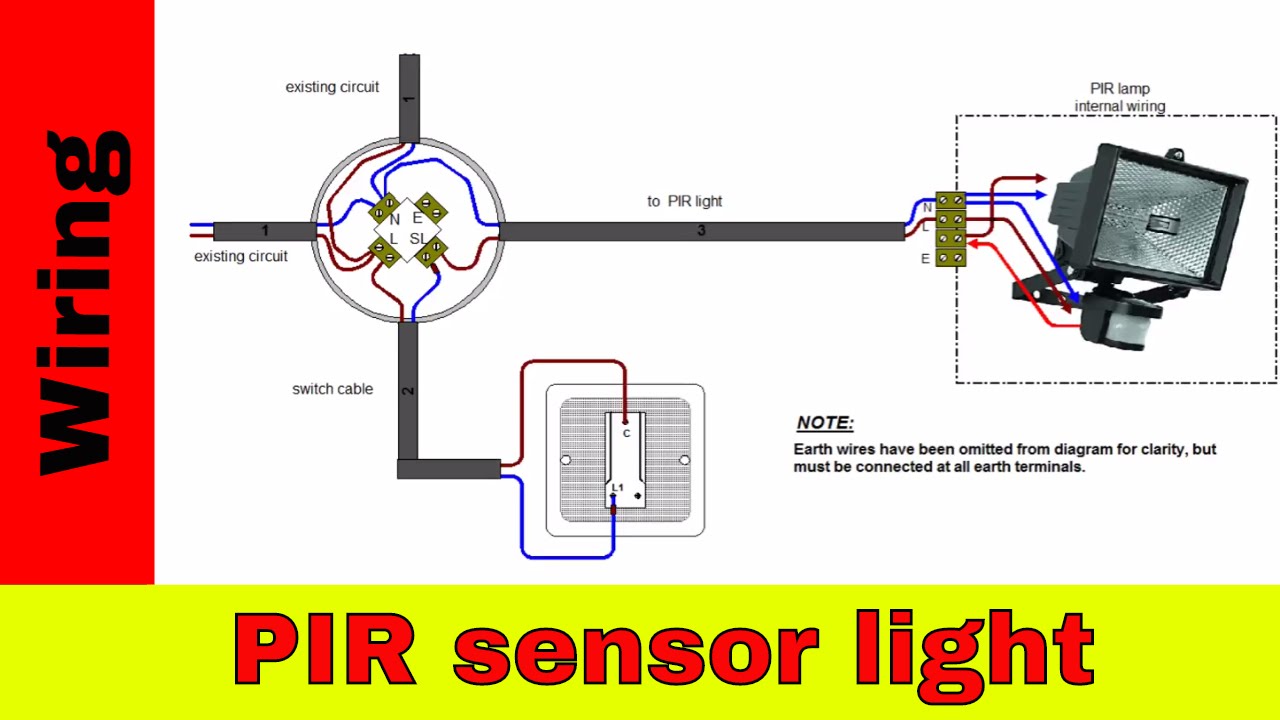
The wiring diagram for a PIR motion sensor light is an essential guide for installing and connecting the sensor to a light fixture. This diagram illustrates the proper wiring connections, ensuring that the sensor functions correctly and triggers the light when motion is detected.

Pir Motion Sensor Light Wiring Diagram Wiring Diagram Schemas
Welcome to @Electrical technologiesToday we learn PIR sensor switch wiring with detailsPIR Motion Sensor Switch Wiring Diagram If you new on channel subscrib.

How to Use PIR Sensor module with Arduino Arduino Project Hub
Texecom PIR Wiring Diagram: Step-by-Step Guide When it comes to installing a Texecom PIR (Passive Infrared) sensor, it's essential to understand the wiring diagram in order to ensure proper installation and functionality. A PIR sensor is commonly used in security systems to detect motion in a given area.

Wiring Diagram For Pir Light Sensor Wiring Draw And Schematic
PIR sensors, or Passive Infrared sensors, are electronic devices that detect infrared radiation (heat) emitted by objects within their field of view. They are commonly used in motion detection systems, such as security alarms, automatic doors, and lighting control systems.
Bestio 3 Wire Pir Motion Sensor Wiring Diagram
How To Wire PIR Motion Sensor Light Switch Pammvi Group is a Distributor & Stockist Of PIR Motion Sensor 462 subscribers Subscribe Subscribed 239 Share 312K views 7 years ago How To.

How to use PIR motion sensor with Arduino
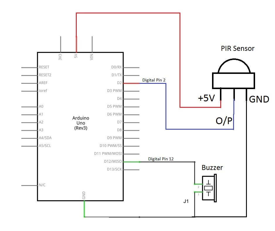
In the connection diagram, you can see that GND is connected with Pin 1, the second pin is connected to Pin 2 and the third pin is connected to the VCC +5 volts. The output of the PIR sensor is HIGH and LOW which means it has zero or 5 volts. Wiring Diagram. Please connect the PIR sensor to Arduino according to the following picture: Wiring Diagram
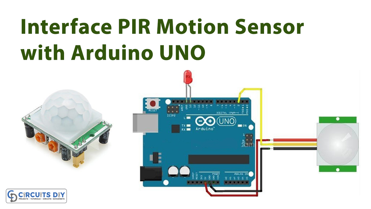
How to Interface PIR Motion Sensor with Arduino UNO
How to wire PIR sensor light. AboutElectricity 56.8K subscribers Subscribe 669 391K views 6 years ago Electrical Wiring and diagrams. In this video you will see how to wire PIR.

ESP32PIRMotionSensorWiringDiagram Random Nerd Tutorials
Section 2: Wiring Diagrams for Multiple PIR Sensors When it comes to wiring multiple PIR (Passive Infrared) sensors, there are a few different options to consider. The specific circuit layout will depend on the number of sensors you are using and the desired functionality. Option 1: Parallel Wiring
PIR Motion Sensor Switch Wiring Diagram YouTube
PIR Sensor Wiring Diagrams It is important to refer to the manufacturer's wiring diagrams when wiring a PIR sensor. These diagrams show which connections need to be made between the power source, PIR sensor, and load. Generally, these diagrams will feature the following components: positive pole of the power source, negative pole of the power.
Detecting Motion Using a PIR Sensor, ESP8266, and Mongoose OS
Wiring diagrams are visual representations of how the motion sensor should be wired, indicating the necessary connection points. Most PIR motion sensors come with their own wiring diagrams, which will show the exact location for each component.

Lap Pir Sensor Wiring Diagram
In this article, I have included a wiring diagram and example codes so you can start experimenting with your sensor. After each example, I break down and explain how the code works, so you should have no problems modifying it to suit your needs. First I will show you how you can use the HC-SR501 as a standalone unit.
pir motion sensor circuit diagram
In this step-by-step diagram guide, we will walk you through the process of wiring two PIR sensors and explain how they can work together to enhance the effectiveness of your security system. By connecting multiple PIR sensors, you can cover a larger area and minimize blind spots, ensuring that any movement within the designated area is.